Address
304 North Cardinal St.
Dorchester Center, MA 02124
Work Hours
Monday to Friday: 7AM - 7PM
Weekend: 10AM - 5PM

Address
304 North Cardinal St.
Dorchester Center, MA 02124
Work Hours
Monday to Friday: 7AM - 7PM
Weekend: 10AM - 5PM

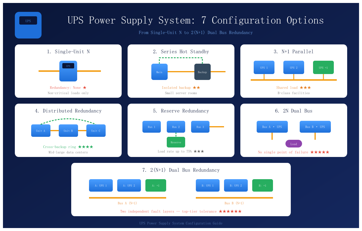
UPS power supply system configuration comparison diagram
A robust UPS power supply system sets the uptime ceiling for any data center. Architecture decisions matter most. However, many engineers struggle to balance redundancy, cost, and maintainability. This guide simplifies that choice. Below, we unpack seven proven configurations. Moreover, we share practical selection advice for real projects.
Uptime Institute research shows human error drives most power failures. Therefore, a sound UPS power supply system must support safe maintenance, not just extra hardware. China’s GB 50174 code requires 2N or equivalent for A-class data centers. Tier IV targets raise the bar further.
Three principles guide every design. First, availability grade dictates redundancy level. Second, shared components create hidden weak points. Third, low load rates hurt efficiency. Consequently, 2N designs demand careful energy planning.
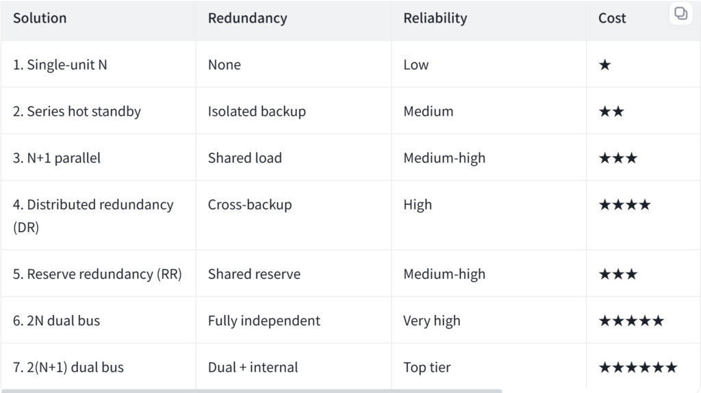
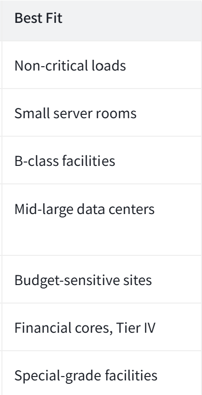
One UPS feeds the entire load through a single path. This setup offers the lowest cost and simplest layout. However, any inverter fault exposes loads to raw utility power. Availability stays at Tier I or II. Thus, this design suits offices and non-critical IT equipment only.
Here, a backup UPS feeds the primary unit’s bypass input. The machines stay electrically isolated. During inverter failure, the load transfers to the backup within 2–8 ms. Meanwhile, brands and sizes may differ freely.
Yet the backup runs idle, so batteries age faster. Moreover, the bypass switch remains a single point of failure. As a result, most new builds prefer N+1 instead.
Two or three identical UPS units share one output bus. Each unit carries an equal load share. When one unit fails, survivors take over instantly. Additionally, overload tolerance improves markedly over series setups.
However, all units must match in model and firmware. Furthermore, the shared bus still couples the machines. Standard GB 51194 recommends this layout for most B-class rooms, limiting parallel units to three.
Three or more identical power trains cross-connect through ATS units. Each train backs up its neighbors. Normal load rates reach 66%, so equipment utilization beats 2N by roughly 30%.
However, ATS control logic grows complex. Besides, switching causes brief voltage dips that sensitive loads must tolerate. Consequently, DR fits cost-aware, fast-growing commercial data centers.
Several running units share one hot reserve through ATS and STS switches. Load rates hit 75%. This yields the highest utilization among multi-unit schemes. Still, the shared reserve becomes critical during faults. Therefore, choose STS units that switch within 4 ms. Fast alert response also matters greatly here.
Two fully independent paths feed every dual-corded load. Nothing overlaps between them. Either bus can fail completely, yet the other carries everything. Hence, this UPS power supply system removes all single points of failure.
Two accessories prove vital. First, STS units serve single-corded devices. Second, LBS units sync both bus outputs. On the downside, investment roughly doubles. Meanwhile, UPS units idle near 40–50% load, lowering efficiency. Even so, A-class sites, banks, and Tier IV facilities adopt this widely.
This scheme stacks N+1 redundancy inside each 2N bus. Two independent fault layers result. One bus may fail entirely while one unit on the other bus also fails. Loads still survive. Naturally, costs and complexity reach the ceiling. Therefore, only special-grade financial and national facilities choose it.
Beyond tier matching, verify true dual utility feeds. Fake dual paths fail together under stress. Also size generators for full IT load plus cooling. Next, avoid nameplate sums; apply coincidence factors instead. Finally, modular UPS units turn fixed N+1 promises into flexible, lifecycle-long scaling.
Every UPS power supply system design trades reliability against cost and complexity. No single architecture wins universally. Instead, match the redundancy level to your availability target. Then leave electrical headroom for smooth future upgrades. In short, let business continuity goals drive the topology. Your budget and your uptime will both thank you.