–“Valve First or Shutdown First?” A Question No SOP Can Answer in One Line. Here’s the Decision Logic That Leaks, Loads, and Weather Actually Demand
In real-world cold plate liquid cooling operations, “valve first or shutdown first” is never a fixed choice. It is a dynamic decision driven by four variables: leak location, leak rate, workload priority, and ambient temperature. A wrong sequence widens the fault scope. Worse, a micro-seep can escalate into board-level short circuits or frozen pipe bursts within seconds. This article breaks that field question into four judgment variables.
一、Why the Sequence Is an Engineering Problem, Not an Experience Problem
Cold plate systems typically use deionized water or glycol solution. Unlike immersion fluids, water-based coolant conducts electricity. After six months of service, even coolant starting below 5μS/cm often rises to 50–100μS/cm. One drip onto a GPU, PSU, or motherboard can trigger a short circuit within seconds.
But aggressive liquid isolation carries its own risk. Shutting a branch valve under high load leaves residual coolant inside the cold plate. Chip waste heat then cooks that trapped liquid far past safe limits. This phenomenon — thermal carryover — oxidizes glycol residue, forms acids, and corrodes copper-aluminum joints. It can also push die temperature past the chip’s limits at the moment of shutdown.
Here lies the core conflict: cut the liquid and risk short circuits; cut the power and risk overheating. That is why a sound SOP never states a fixed order. It states judgment conditions.
二、Four Field Conditions That Decide the Sequence
Condition 1: Leak Location — It Defines the Isolation Scope
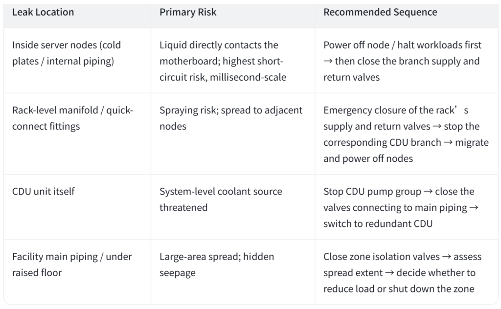
Where the leak sits in the system hierarchy determines the action granularity::
Node-level cold plate or quick-connect seep: The detection cable wraps the cold plate and tubing. The controller sits on the motherboard. After the alert, power off that node first; the cluster migrates workloads. No need to cut the main loop.
In-rack branch pipes or Manifold seep: Close that branch’s inlet and outlet solenoid valves first (response time typically ≤2s). Other nodes in the same rack keep running. Workloads stay intact.
CDU body or main supply pipe leak: Cut the main valve and stop the pumps immediately. No isolation path exists at this level. Continued flow only enlarges the spill.
Facility-level piping or under-floor bridge seep: Trigger the facility-level alert. Close the zone valve, start the drain pump, and cut local power.
Condition 2: Leak Rate — It Defines the Remaining Time Window
Rate determines how many seconds you still have:
Micro-seep (≤50ml, slow drip or wetting): Alert, locate, and notify first. Do not stop the pumps immediately. Close the branch valve before anything else; system pressure still holds stable. Isolate the liquid path first and compress the fault to the smallest unit.
Medium leak (500ml to several liters per minute): Run valve closure and graceful shutdown in parallel. BMC issues a soft-off command (target ≤90s) while the branch valves close. This avoids thermal carryover.
Jet-type major leak (visible spray or pressure drop >0.05MPa/min): Skip all soft procedures. Trip the pumps and cut the main valve at once. Business loss now yields to asset safety. “Valve first” simply means “stop the bleeding first”.
Condition 3: Workload Priority — It Defines How “Soft” the Shutdown Should Be
Standard workloads: Let BMC run a graceful shutdown. Save memory data and storage cache, then close valves.
Mission-critical loads (financial trading, mid-run AI checkpoints, long HPC jobs): Close branch valves first and keep other nodes in the rack online. Cut node power only when isolation fails, and rely on cluster migration to preserve continuity.
Zero-downtime scenarios (edge sites, single-node systems): Design in an N+1 redundant CDU. The backup takes over automatically on leak alerts. Only then does the faulty CDU stop and close valves — invisible to the workload.
Condition 4: Ambient Temperature and Coolant Properties — The Northern Variable
This is the most overlooked — and most expensive — condition:
Cold-climate regions (e.g., Helingerr data center parks) require glycol concentration ≥35% in winter. Below that, the freezing point climbs and pipes can burst from ice expansion.
In sub-zero environments, never stop the pump before closing valves. Dead water segments freeze fast. The correct order: close the valve first to stop the leak, keep low-flow circulation or start heat tracing, then shut down and drain.
Conversely, in hot summer with high load, closing the valve first traps hot coolant in the cold plate. Thermal carryover peaks here. So: derate or soft-shutdown first, close the valve second.
三、Why a One-Size-Fits-All SOP Fails
Many playbooks copy a single line: “shut down immediately on leak alert” or “close valves immediately.” Such blanket rules fail in the field:
“Always close the valve first” — under high summer load, thermal carryover burns out the trapped coolant loop.
“Always shut down first” — in sub-zero winters, dead water segments crack the pipes. With a jet-type major leak, several liters of glycol escape during the 90-second graceful window.
The right approach: encode the decision matrix into BMS/DCIM interlock logic. The system reads sensor inputs — leak location, pressure-drop rate, estimated leak volume, load temperature, ambient temperature — and auto-selects a playbook. Operators then only confirm and review.
四、Interlock Logic and SOP Implementation
A field-proven leak-response SOP contains four layers:
1. Detection layer: three tiers, never rely on one sensor
Node level: cold plate detection cables with real-time BMC telemetry;
Rack level: leak sensing ropes along the rack base, below the Manifold, and under cable trays — never suspended;
Facility level: under-floor water ropes + pressure sensors on both supply and return mains + flow-differential monitoring.
2. Decision layer: turn four variables into condition branches
Pressure-drop rate → decides whether to skip soft procedures and trip directly;
Load and ambient temperature → sets the pre-valve action (derate / soft shutdown / keep circulating).
3. Execution layer: sequence control between valve and shutdown
Motorized ball valves must close within 6 seconds;
BMC graceful shutdown targets ≤90 seconds;
Two-person interlock: one operates, one supervises; DCIM and BMS issue commands through dual channels to prevent single-point errors.
4. Review layer: never skip drills
Run at least one leak-response drill per year. Cover three scenarios: micro-seep, main pipe major leak, and sub-zero shutdown. Validate 28 key action metrics. Review alert redundancy, false-alarm rate, and response latency.
Conclusion
Leak response in cold plate liquid cooling is a race between information completeness and the shrinking time window. Four field variables — leak location, leak rate, workload priority, and ambient temperature — together decide whether the valve or the shutdown comes first. Encode them into the SOP’s decision matrix. Never leave them in an operator’s muscle memory. That step marks when a liquid cooling system truly reaches engineering maturity.
Safety never reduces to a single line: “valve first” or “shutdown first.”